RDS 2024
Robot Finger + Thumb with Wearable Haptic Interface
Robot Design Studio Overview
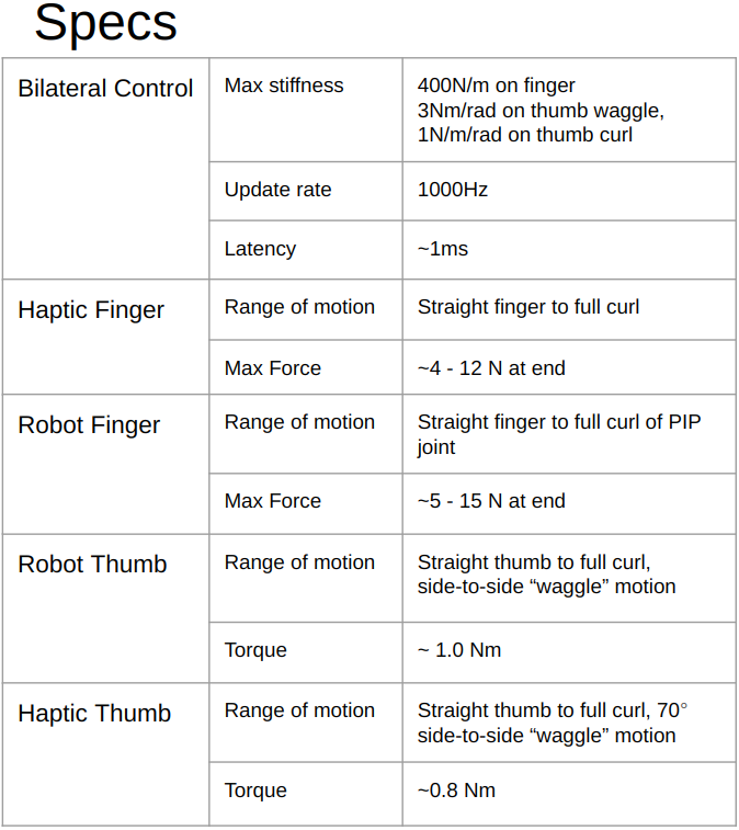
The overarching goal of Robot Design Studio (RDS) is to learn how to design, build, operate, characterize, and refine a high-performance robotic system. The course is a two-quarter capstone project course at Northwestern University, co-instructed by Dr. J. Edward Colgate and myself for the 2024 Winter and Spring school quarters. For RDS 2024, the goal was to develop a robotic gripper and haptic interface for usage in hazardous laboratory experiments, such as with radiation hotbox environments for chemistry research. The desired capabilities are the ability to pinch, twist, and hold lab objects such as test tubes. We gave the design parameters of 2 motors and 3 degrees of freedom per finger with at least one synergistic or passive joint.
Team Formation
The class consisted of 20 senior-level undergraduate and graduate engineering students who were split into a hybrid team structure devised by myself. Each student would be a member of two types of teams: a primary "project team" and secondary "specialization committee". There are four project teams: Robot Thumb, Robot Finger, Haptic Thumb, Haptic Finger, and four specialization committees: Mechanical/Manufacturing, Electrical, Software, and System Integration. Each project team would require a member from each committee and vice versa. This team structure was designed to create a more cohesive and connected collective team towards the final goals of the project. This also provides a support network for interteam collaboration and coordination.
Design
The teams were prompted to rapidly iterate on their mechanical designs in conjunction with biweekly meetings with the instruction staff for feedback and guidance. The motor remotization and transmission were designed to be cable-driven systems using pulleys and tendons to transmit the torques to each link of the fingers. The teams were instructed to keep in mind the mutual mounting capabilities of their devices so that they may design their fingers separately, but then bring the designs together at the end for a useful and intuitive workspace and range of motion. The most tedious element of the system, as reported by the students, was the tendon routing and tensioning for low backlash and high stiffness actuation.
Robot Gripper
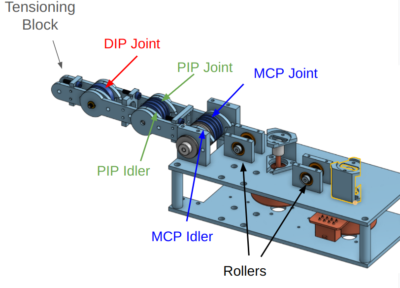
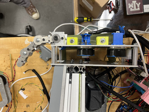
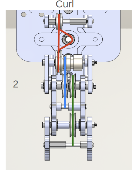
The Gripper consists of a robot finger and thumb. The degrees of freedom for the finger included the curl action of the human index finger, where each joint has parallel axes. The joint lengths were designed after generic human hand model dimensions, with motors that provided an adequate amount of torque and speed for lifting and manipulating small laboratory objects.
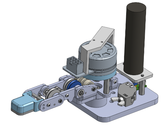
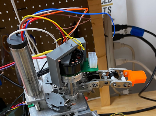
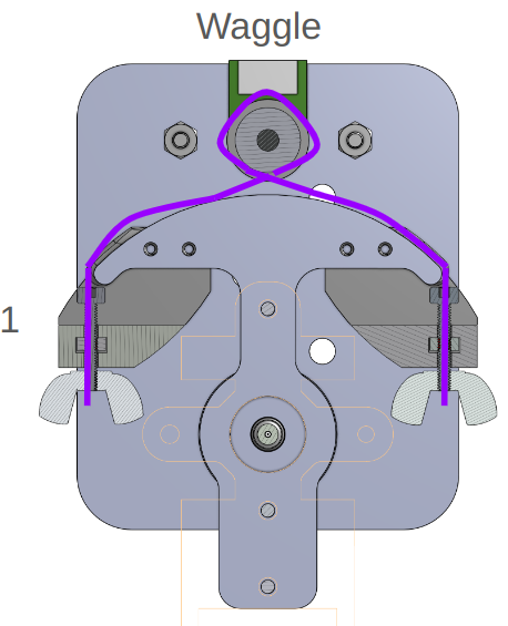
The Robot thumb included degrees of freedom for the curling motion of the thumb as well as what students called the "wag" (abduction/adduction) motion.
Haptic Device
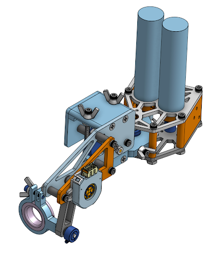
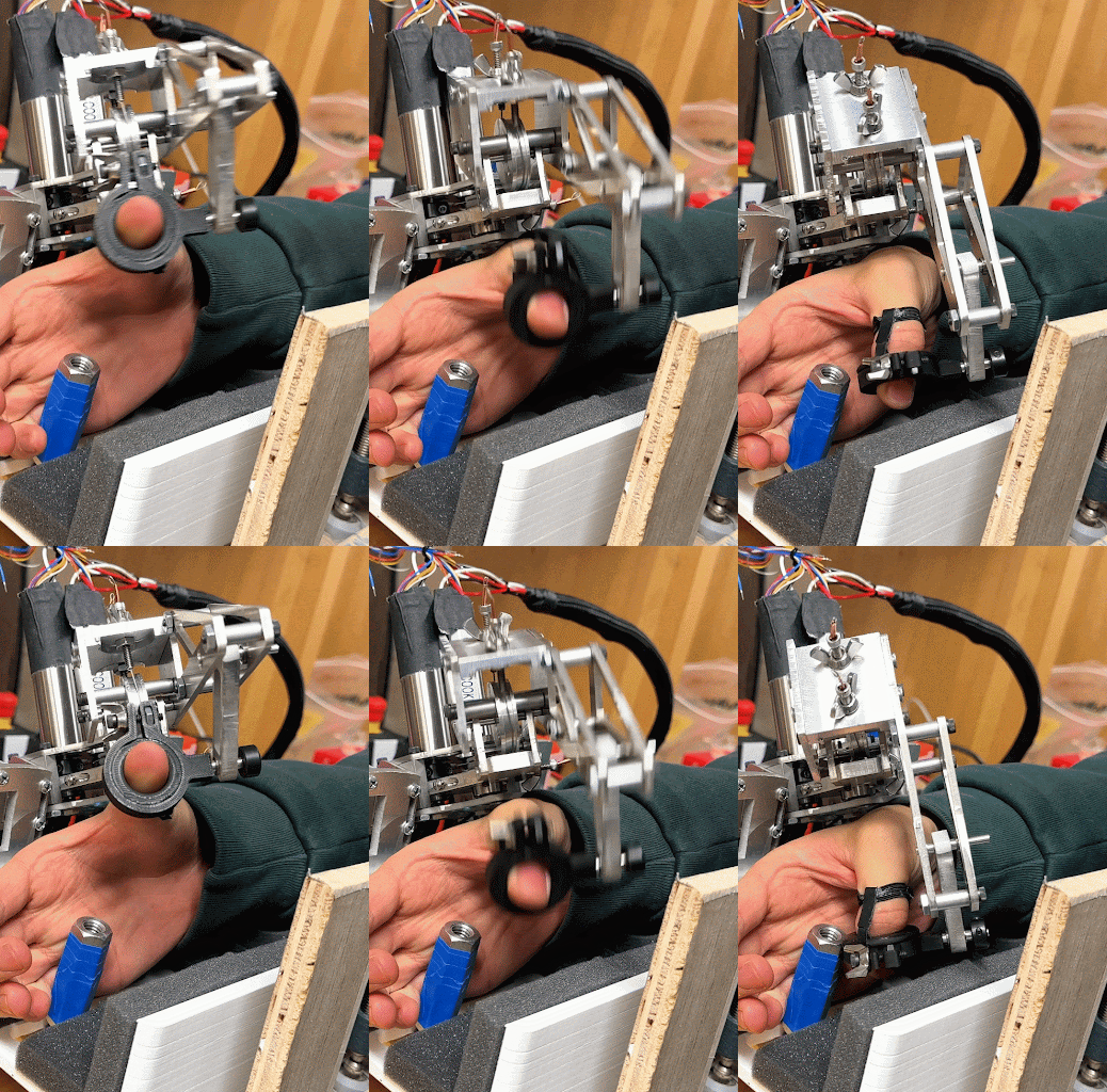
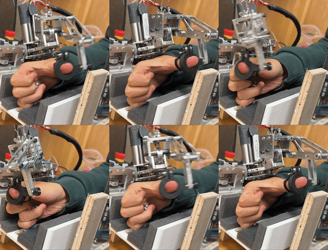
The Haptic device is an exoskeletal finger and thumb apparatus that has the same degrees of freedom (DOF) and range of motion (ROM) parameters as the Robot Gripper system. The haptic device functions as a controller, DOF constraint, and force feedback mechanism. It has similar motor specifications so that the robot and haptic systems may be more similar in the forces you can feel and impart on objects.
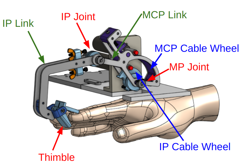
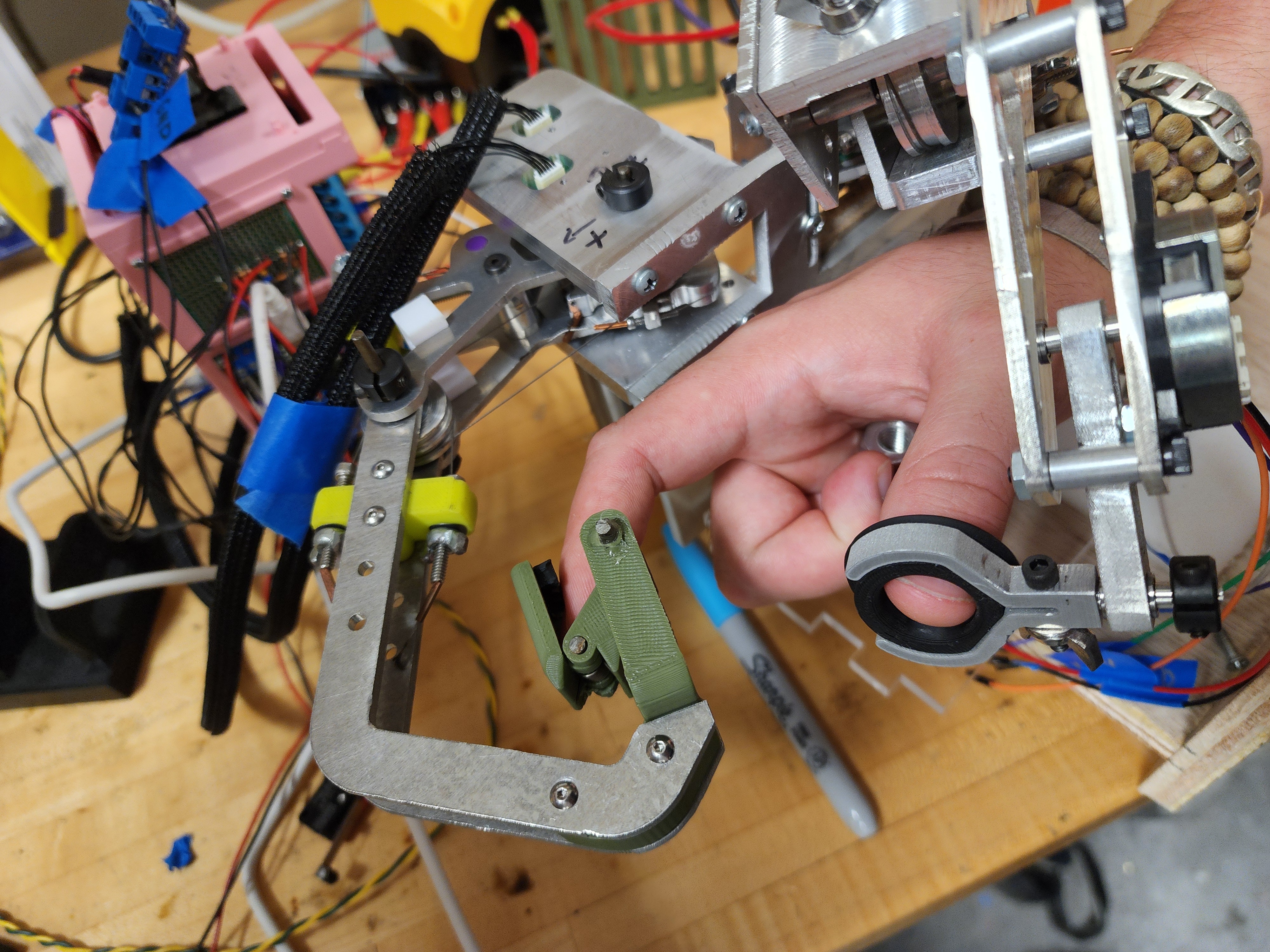
The haptic system is linked to the robot gripper using bilateral control. The only sensors on the entire system include Hall effect encoders on the motor outputs and an absolute encoder on the haptic thumb curl joint. The forces are sensed through the motors.
The selection of the DOFs for the haptic system was chosen for optimal pinching and manipulation actions. The wag motion of the thumb was the product of a design pivot to provide a more intuitive pinching motion.
Cable Drive
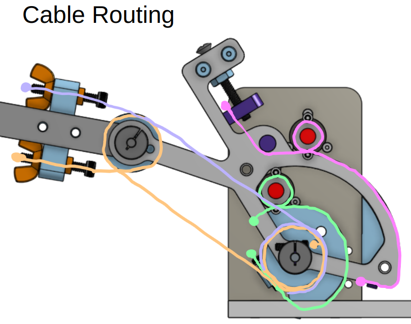
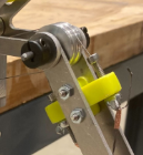
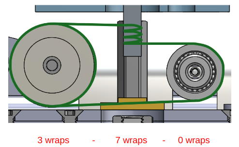
The cable drive systems used in all of the systems employed thin steel cables that remote the motor torque to each joint. Usually, the joint nearest the motors formed a capstan cable drive mechanism. The students chose to use steel cables with brass crimps for terminations. Tensioning mechanisms were designed to be accessible and adjustable. The iterations on each project usually led to terminating the cable at a vented screw, where the tension would be adjusted by turning a nut or wing-nut to tighten said screw, changing the amount of cable and tension available.
Remotization
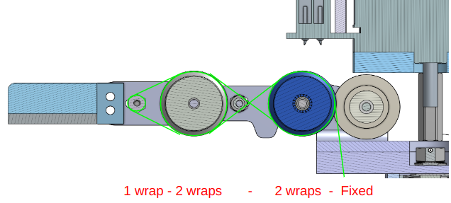
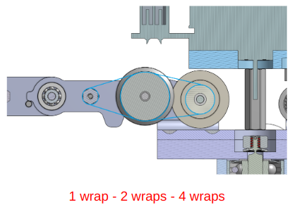
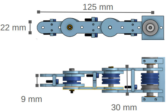
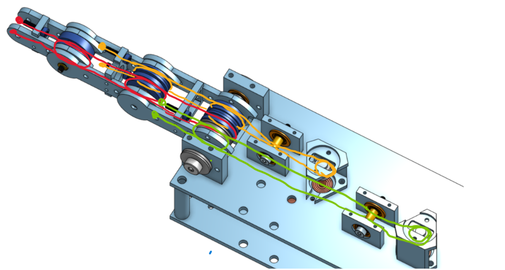
To remote the joints from the motors, the students used cable routing and careful placement of terminations for each cable drive system to get the desired range of motion and transmission for each joint, as well as to minimize joint coupling where possible. Using routing techniques such as routing cables through the center of rotation to remove coupling worked well, even for more complex systems such as the haptic thumb system.
Robot Thumb Routing
Robot Finger Routing

Haptic Thumb Routing
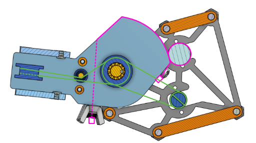
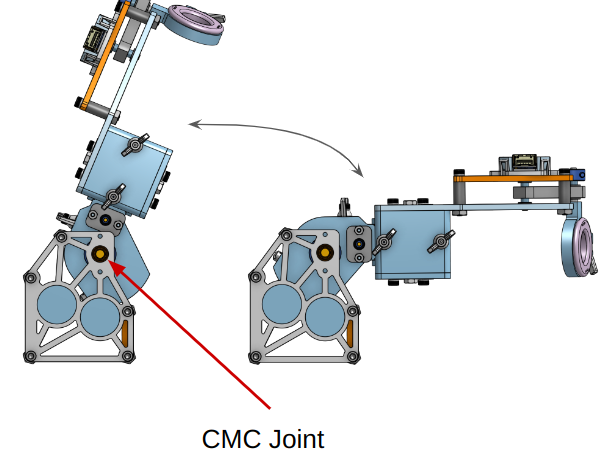
Haptic Finger Routing

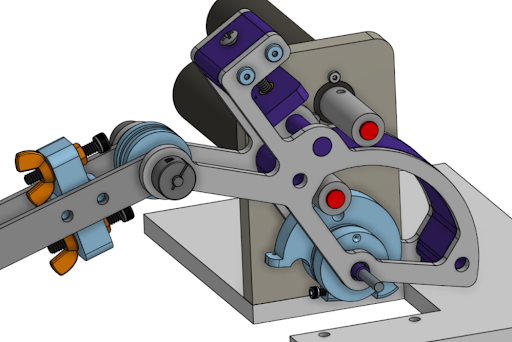
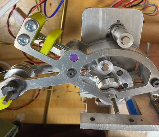
Electronic Hardware
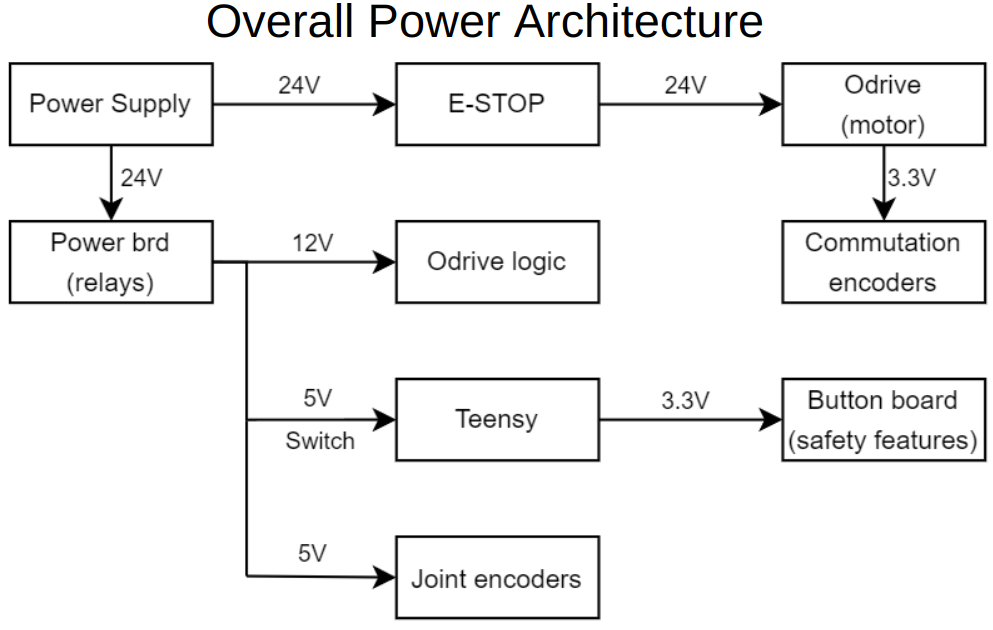
The motors selected to meet the required parameters were the ECX Torque 22XL and the EC 45 Flat Maxon motors. The robot finger used 2 flat motors, the robot thumb used one of each motor, the rest of the systems motors were ECX 22XL motors. Each motor is driven by its own ODrive Pro, trading torque requests and encoder positions with a Teensy 4.1 microcontroller via a controller-area network (CAN). The Teensies would communicate to eachother via CAN bus communicating positions, safety info, and heartbeat signals. The overall power architecture is shown in the diagram below.
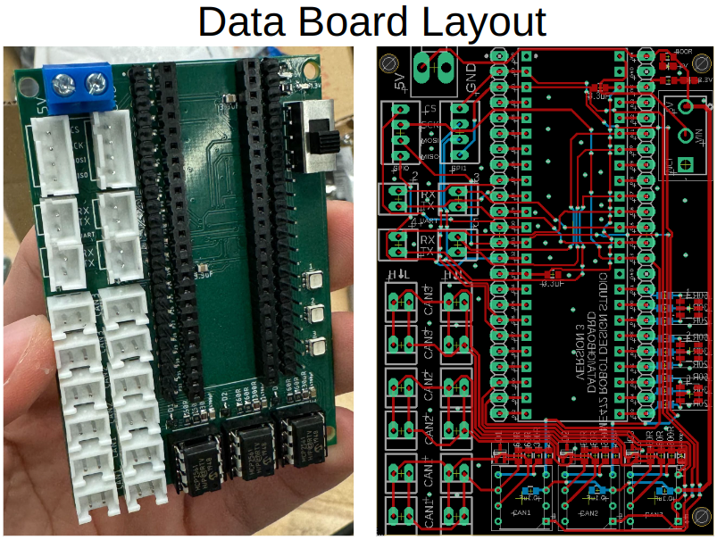
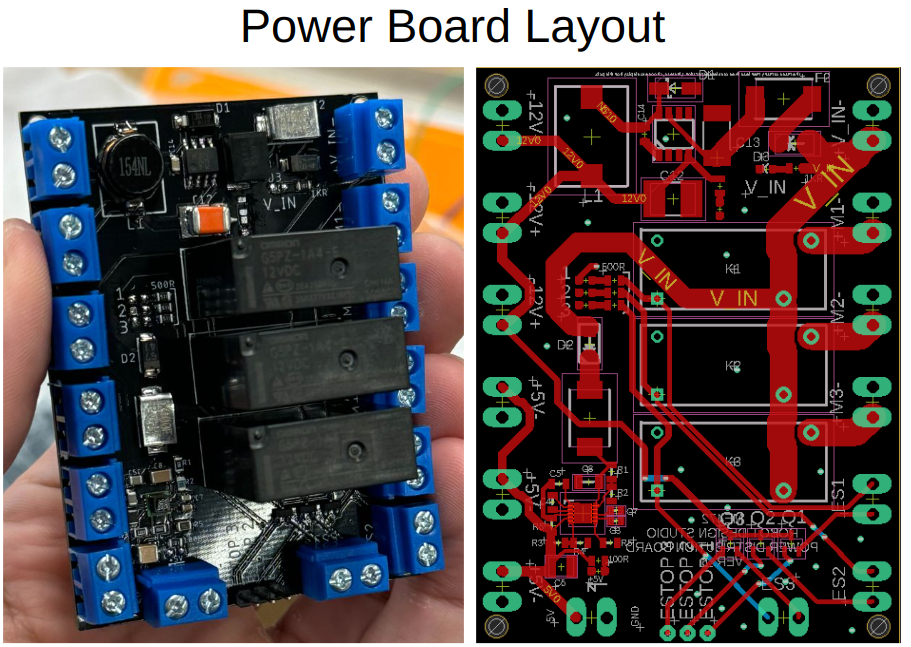
PCBs were designed to handle the intercommunication between the Teensies as well as the power distrobution.
Controls
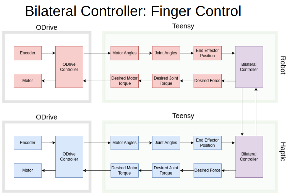
The robot and haptic systems were controlled using bilateral control designed to have the robotic system mirror the haptic system and vice versa. The finger control loop and the thumb control loop are slightly different because the fingers would match end effector positions where the thumbs would match just joint angles. The positions are connected using a virtual spring-damper controller
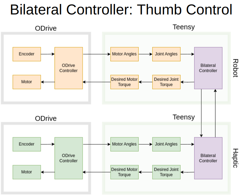
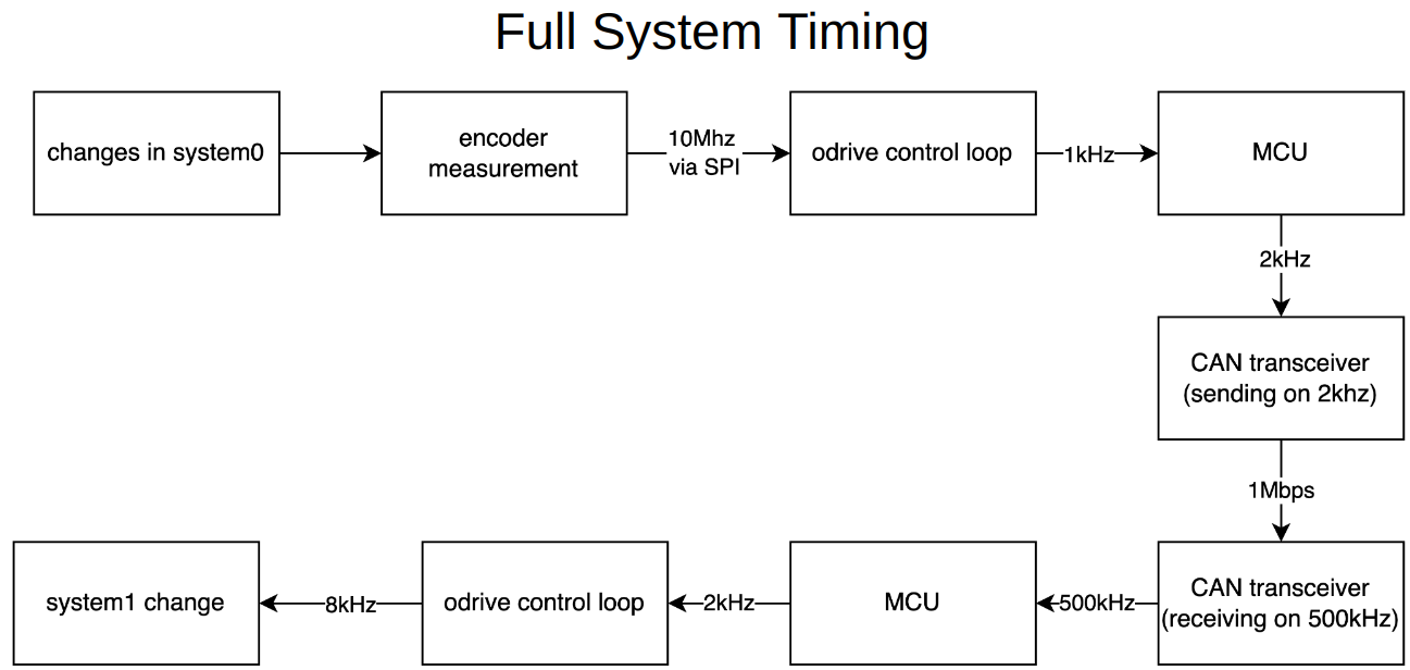
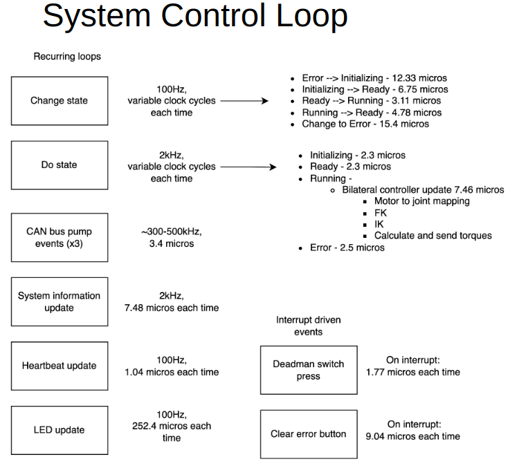
Pipeline
These diagrams show the speeds and location of the system loop.
Mapping
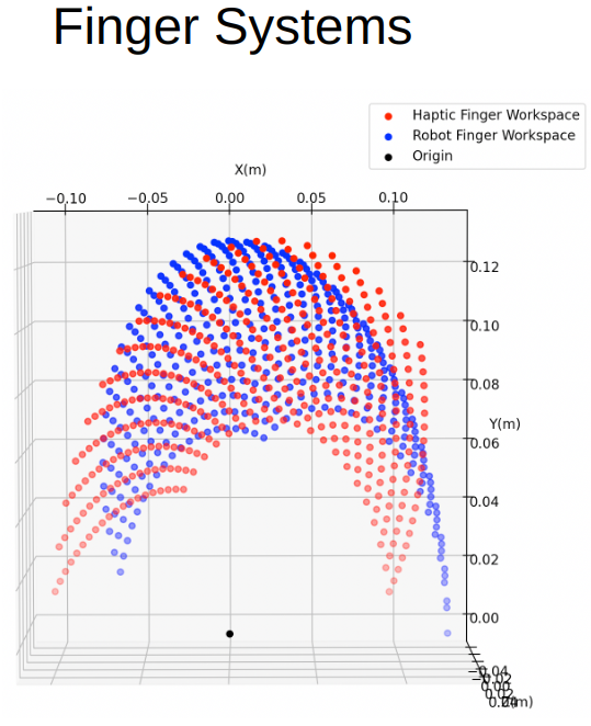
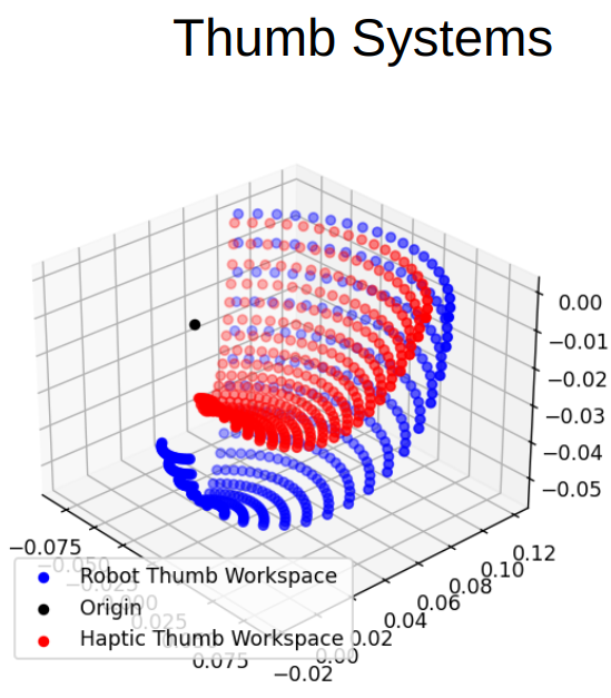
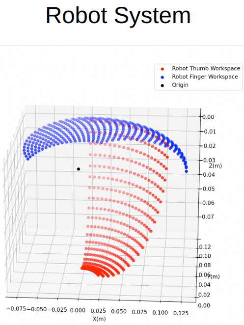
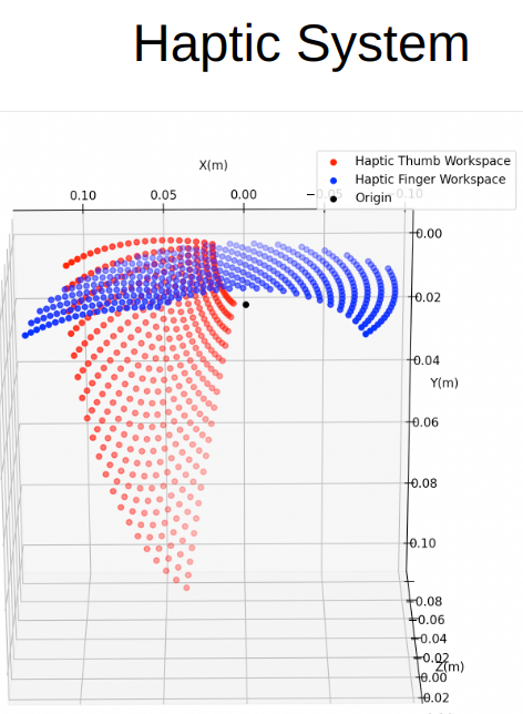
Each finger system only communicates with its haptic counterpart. The Finger mapping occurs between the end effector positions. The Thumb mapping occurs between the joint positions because of 3D workspace and kinematic differences between the thumb interfaces. Below there are workspace diagrams that display in three dimensions a spread of the workspaces for each system and how it compares with its counterparts. The first diagrams show the workspace comparison between the finger and thumb systems, where the other diagrams show the complete workspace of the entire robot system and entire haptic system.
Videos
Acknowledgement: Thank you to Dr. Edward Colgate and Northwestern University for allowing me to instruct and direct this course.