Robot Feet
This project started as a literature review of robotic feet for bipedal humanoid robots. There was also extensive research in what type of sensor would be ideal for robot feet considering COP and ground sensing. The findings of the literature review and sensor research were used to design many novel prototype feet that were considered for the NADIA robot. This led to the specification, commissioning, and testing of a 6-axis force/torque sensor. The testing and implementation of the foot sensor continued throughout my time at the IHMC.
Literature Review
My literature review was focused on dynamic robot feet both actuated and passive with the goal to increase efficiency and ability for robotic bipedal locomotion. I covered humanoid robots from all over the world including Atlas, ASIMO, HRP, LOLA, Sarcos, TORO, Cassie, Digit, WABIAN, and many more. My studies showed that having an additional toe linkage would result in a more human-like walking gait and more efficient force transfer throughout locomotion. With toes, the robot would perform a more natural toe-off and heel strike action that improved efficiency by reducing the maximum torque required for forward movement. The toe-off/heel-strike gait also improves efficiency by reducing the lateral movement range of the torso during locomotion, leading to more consistent force and power requirements. The addition of toes would also create a more efficient "roll-over shape" which would improve the efficiency for dynamic walking.
Sensor
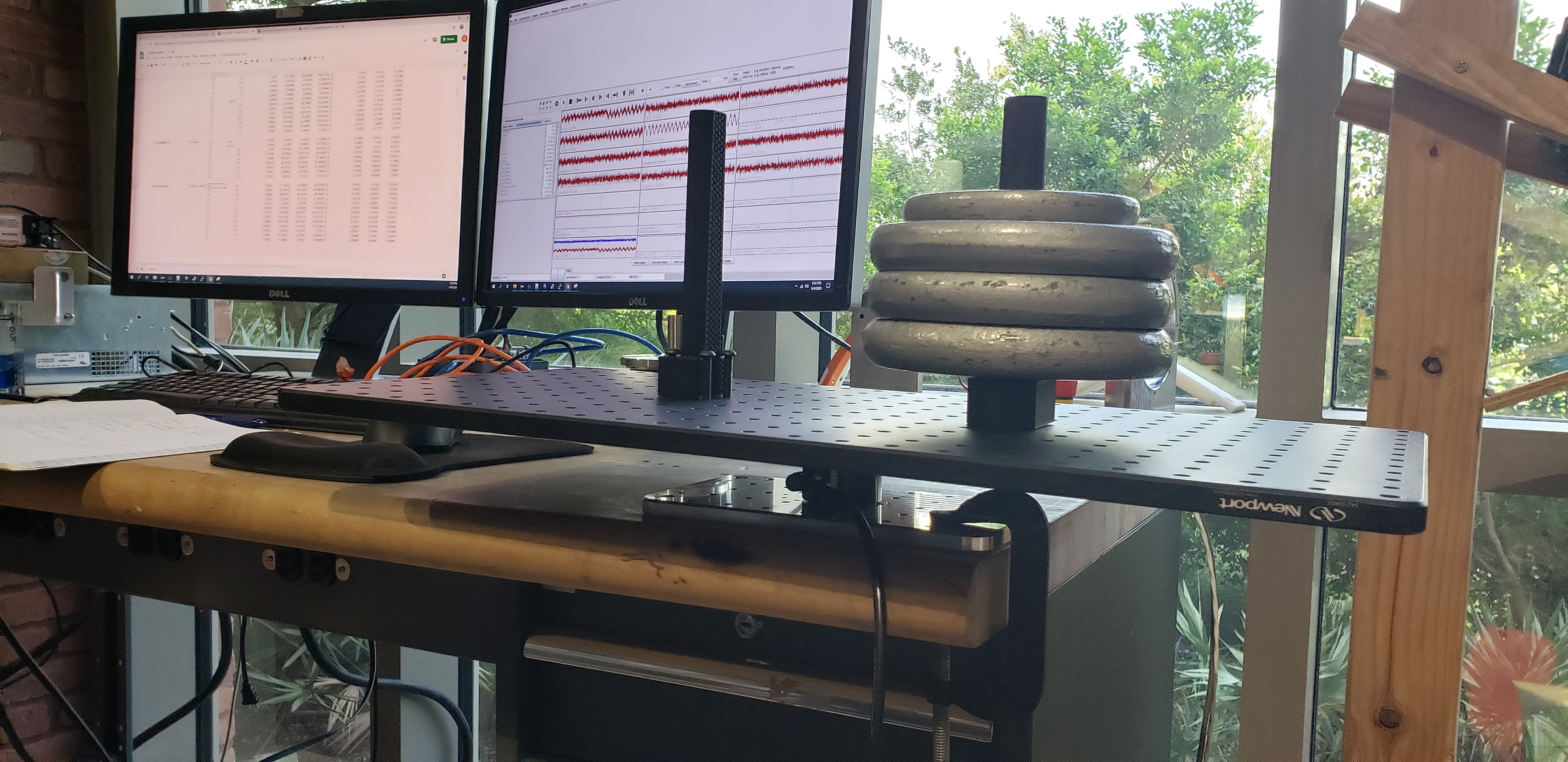
The robotic foot sensors need to be able to sense the center of pressure from the foot to the ground. To do this, you need to be able to sense 3 axes of force; x-moment, y-moment, z-axial. I decided to move forward with a 6-axis force/torque sensor that measures all moment torques and all axial forces. I conducted a variety of tests on the 6-axis F/T sensor, including force measurement resolution, historesis testing, thermal drift testing, and long term measurement drift.
Photos of load testing setup
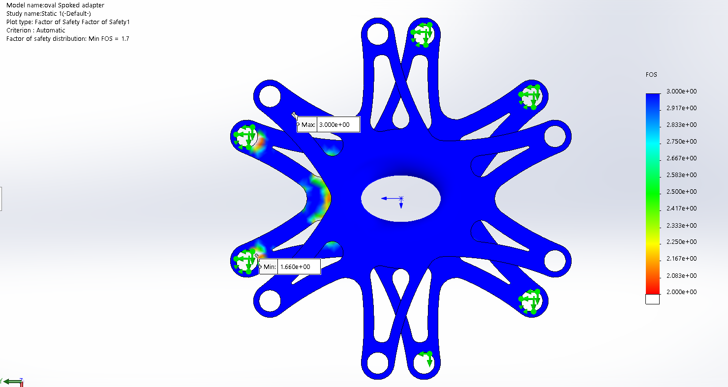
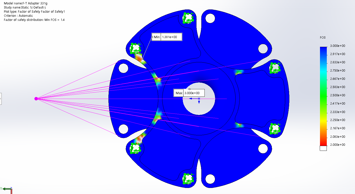
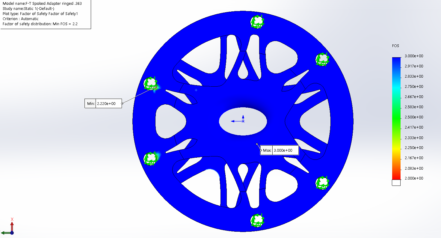
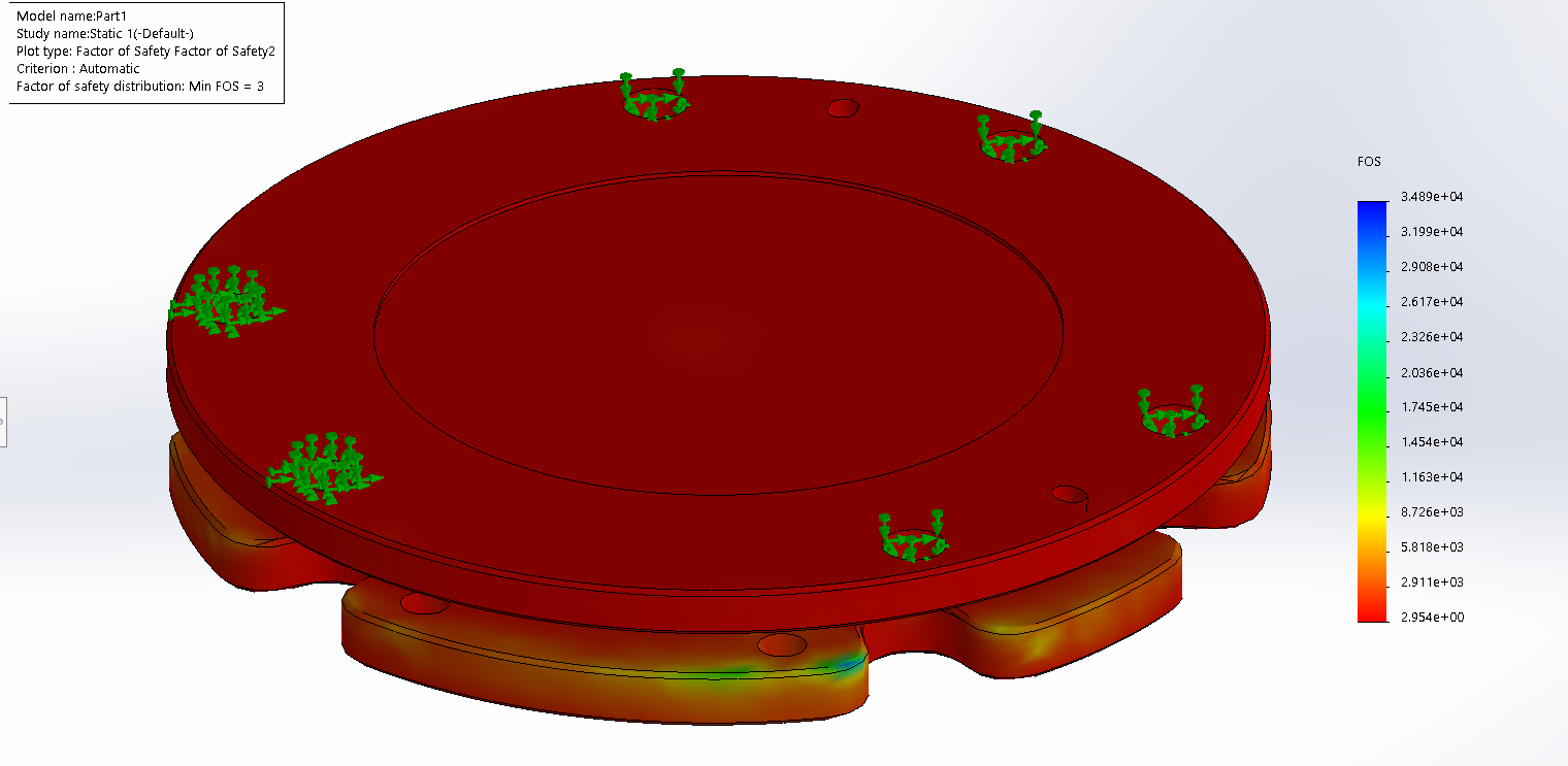
My test results led to the discovery of inaccurate measurements due to sensor housing deformation between the mounting holes. To mitigate this, I designed and conducted FEA on adapter components that would attach to the deforming surfaces to translate the forces through a structure that would spread the forces evenly between each mounting holes, eliminating housing deformation. I tested different designs in Solidworks an attempt to reduce added height and weight.
Design and Prototyping
My initial foot designs included toe linkages that would bring the added benefits to the robot gait. I made these designs with the current sensor structure in mind and was able to print plastic prototypes to demonstrate the movement of the toes.
CAD and printed model of foot with toes
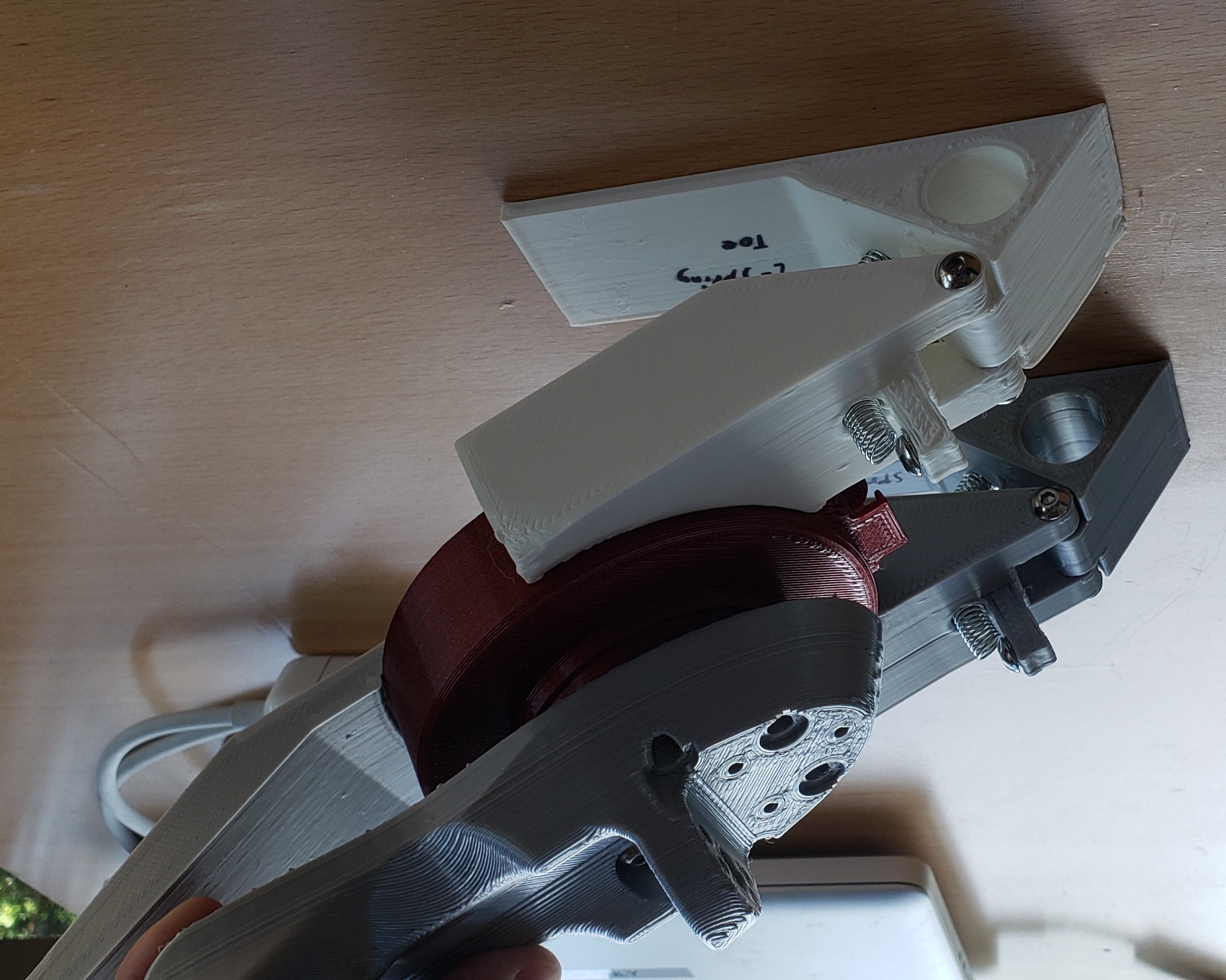
With the limited literature and implementation of toes on robots, the final decision was to not add toes to the NADIA robot foot. Adding the toe linkage would increase the degree of freedom of the robot and add a large amount of complexity to the control system. The developed robot balance and locomotion control system was also not designed to perform with a natural human gait and would need a large amount of redevelopment to implement. The toes would also require strong actuators, which would be large and heavy, increasing the inertial load to swing the leg forward. At the current development of the robot, adding toes would add much more complexity that outweighed the benefits of a human-like toe-off/heel-strike gait.
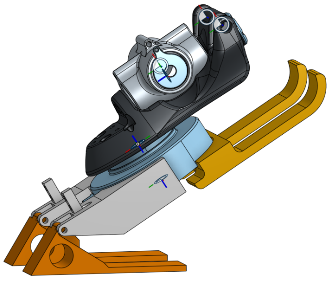
Photo of implemented F/T sensor on flat foot
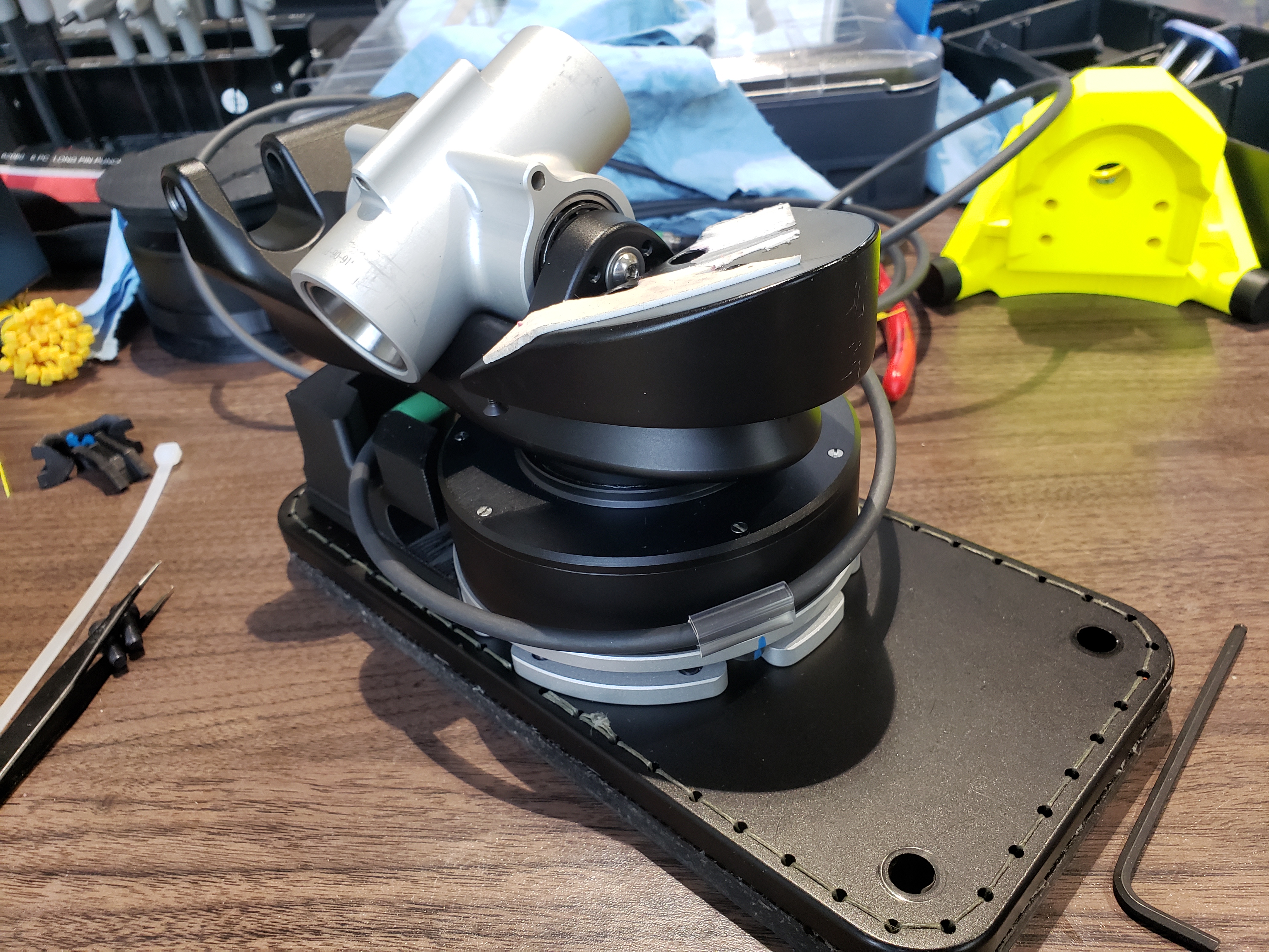
Implementation
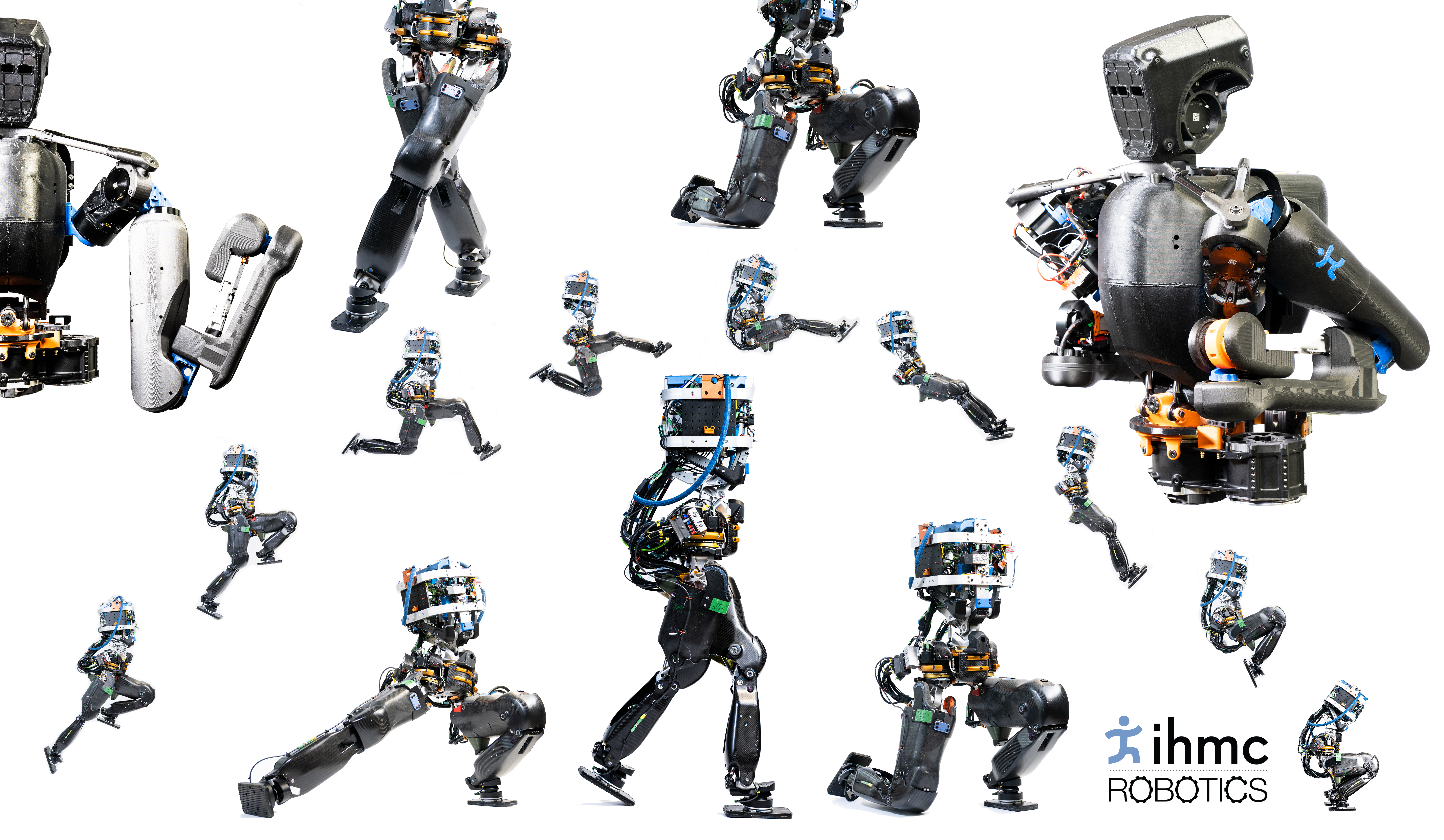
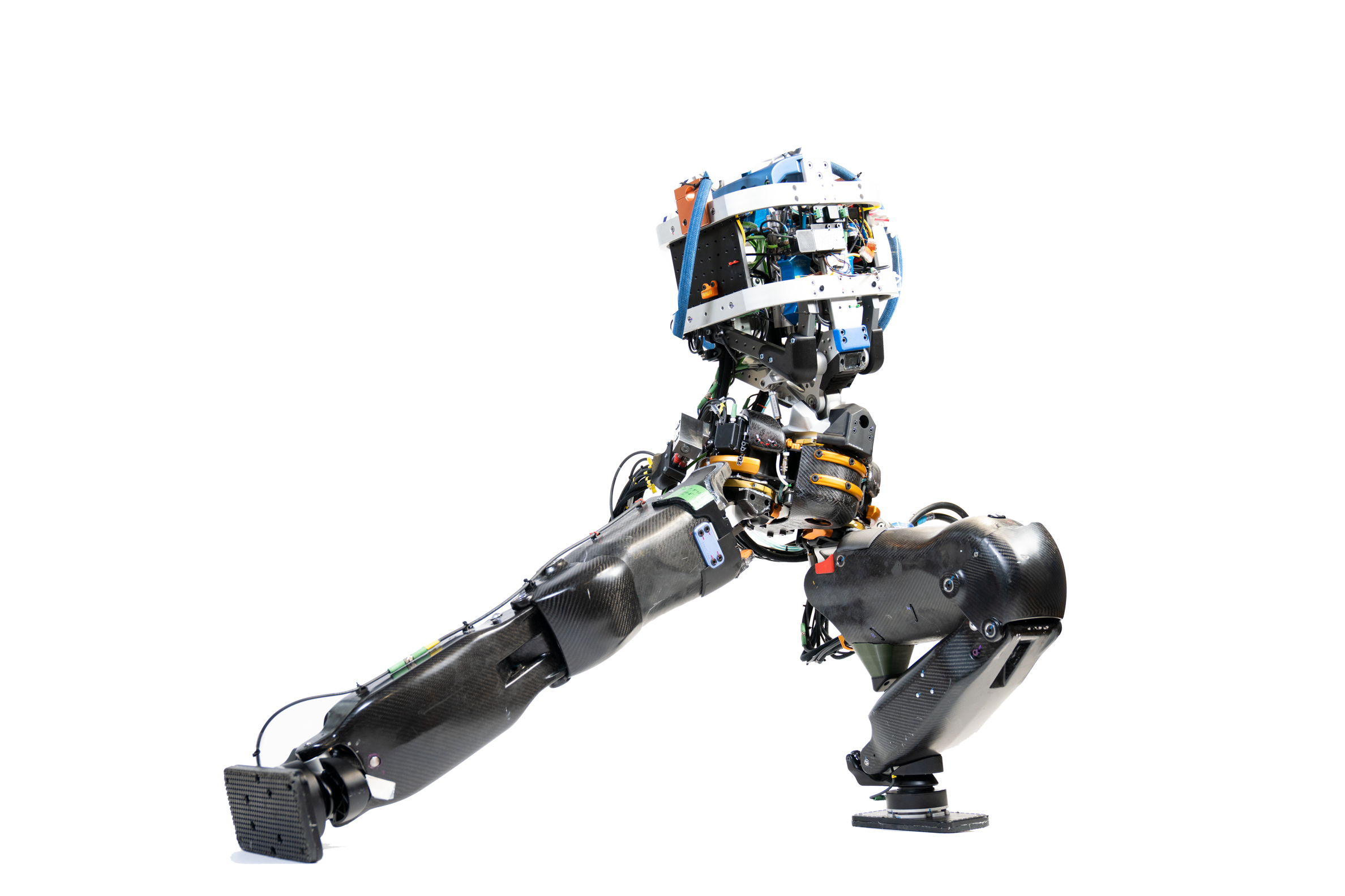
Display of large range of motion of the Nadia legs
Other IHMC NADIA Projects
Carbon Fiber Process
I helped develop a carbon fiber laying process that solved issues presented from previous carbon fiber laying processes. The previous process of creating the shell laid the carbon fiber inside of an outer mold with an inflation system that compressed the layers from the inside. That process would create imperfections on the inside surface that needed constant sanding and grinding in order to not conflict with the components housed inside.
Photo of the carbon fiber thigh with components inside and Inner Shell
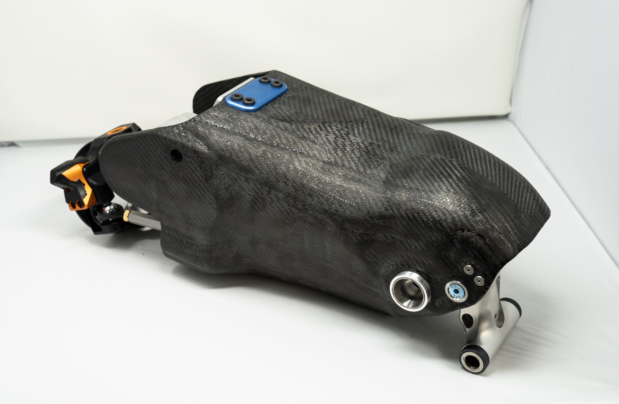
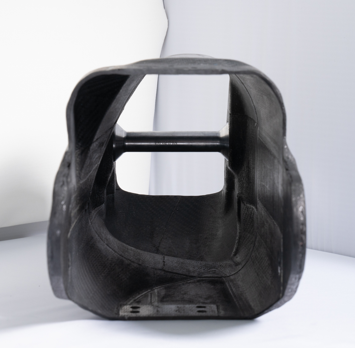
Our new process involved creating a printable inner mold that would collapse inward for easy release and removal. The carbon fiber would be layered over the mold and vacuum sealed for curing. After the part is cured, the core mold would be collapsed and removed in pieces. This allowed us to easily fine tune the topology of the inner surface of the shell, reducing the amount of post processing needed.
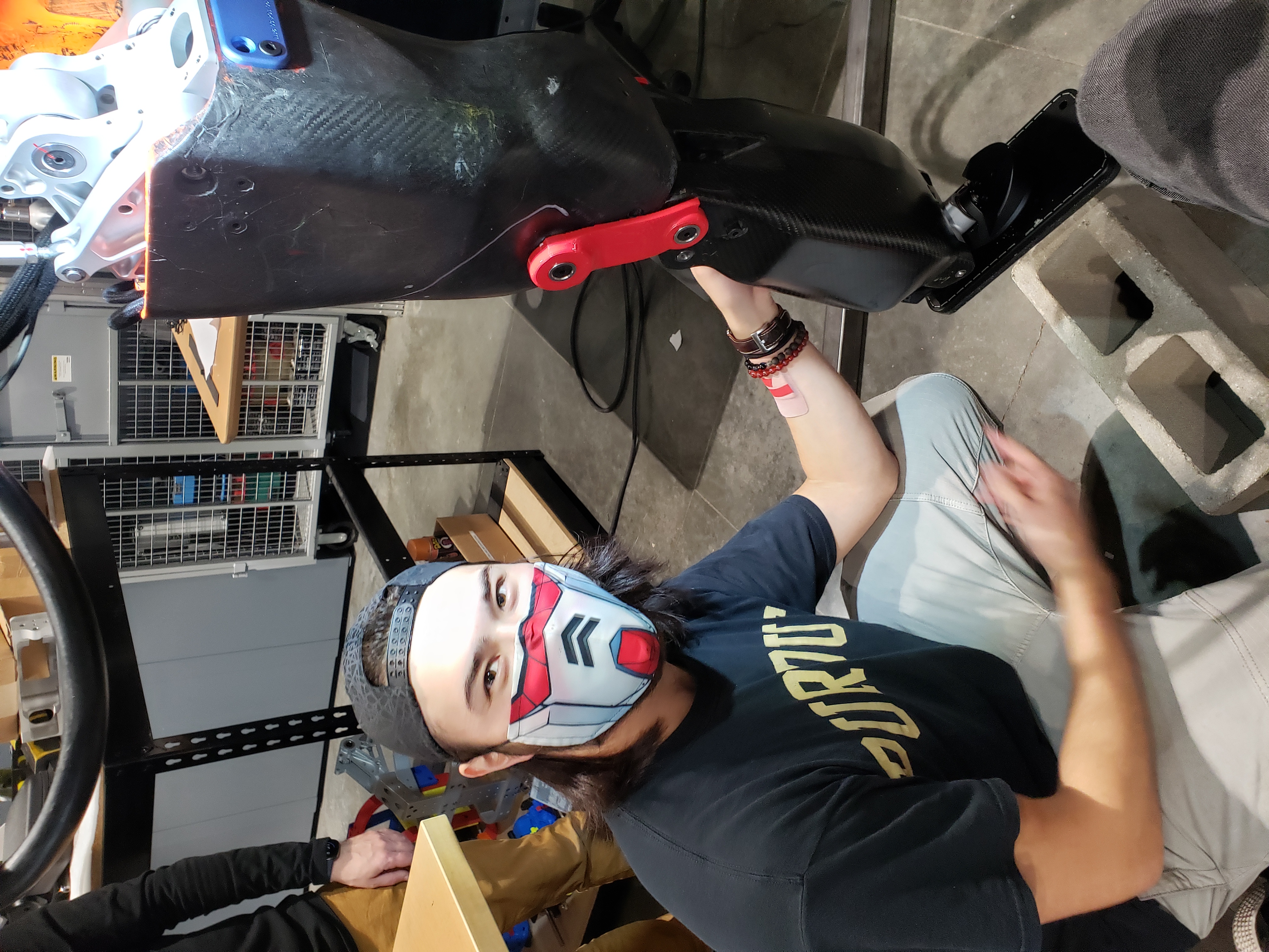
Photo of me after assembling leg
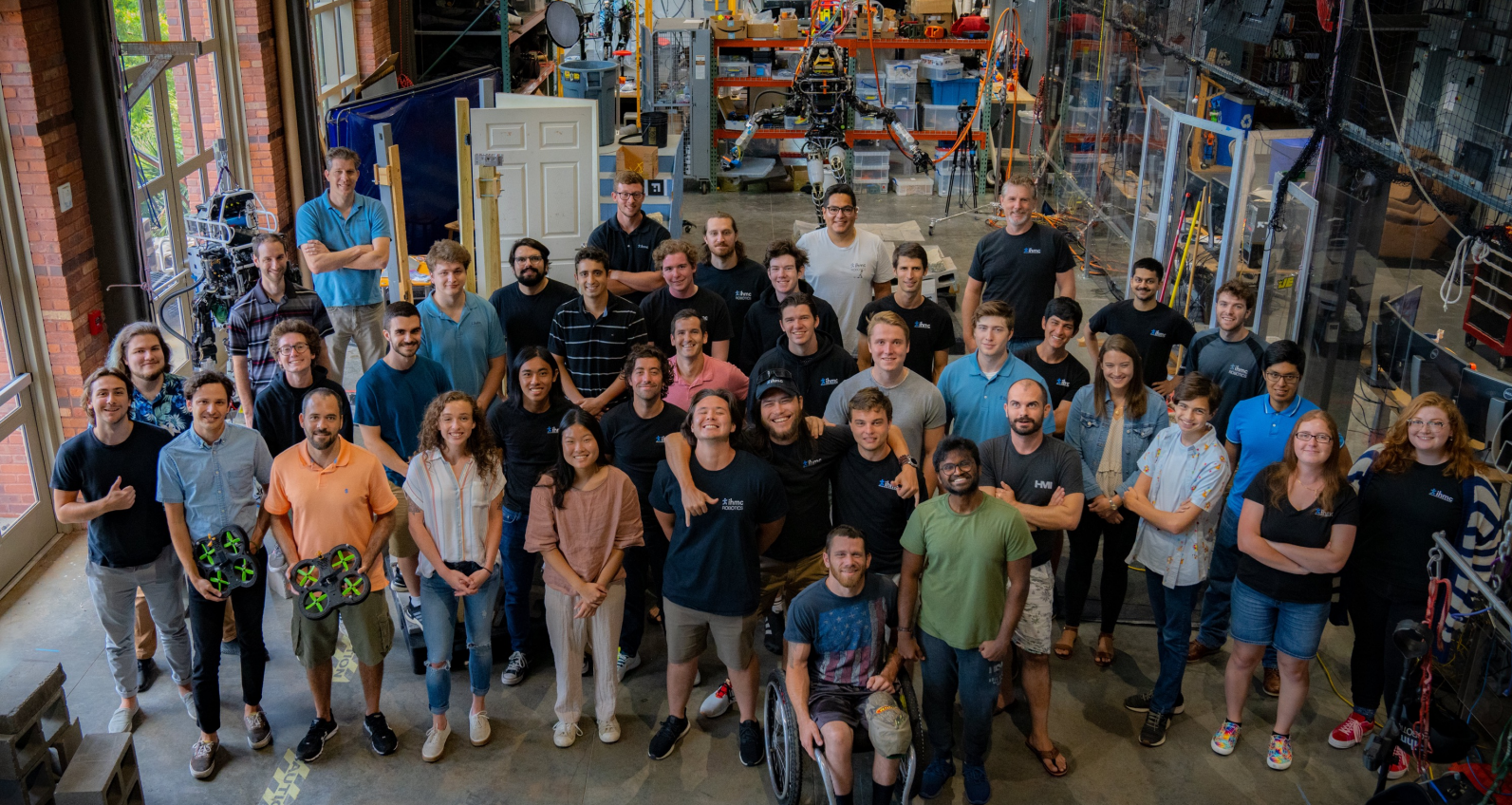
Group photo of the IHMC lab